Connect GPS Receivers or Flight Computers to Nook Simple Touch via Internal UART
Photos and text by Tom Kreyche, with some information sourced from various posts on the XDA Developers Nook ST forum.
The Nook ST has an unused serial port (called ttyS1) that can be used for connecting GPS receivers, flight computers and other equipment. The Nook ST hardware does not include a logic level to RS-232 voltage level translator (also called a transceiver), so one must be added for RS-232 communications.
These instructions cover adding the RS-232 transceiver. You can also use the port directly (without a transceiver) for connecting other devices, such as:
- A logic level GPS module with a serial port, for example a Sparkfun GPS-11571 (the Nook ST can power the GPS module)
- Your own design flight computer via logic level serial port, based on Arduino, mbed or some other embedded system
- A low power Bluetooth or Zigbee radio for wireless serial port communications
Other Uses for the Serial Port on the Nook ST
Top Hat and XCSoar both have built-in support for the ttyS1 serial port. This is uncommon because there is no native Java serial port API on Android-based systems (although it can be read and written with a file stream). As a result, other navigation programs may not recognize the port.Advantages
- Simple and less expensive - does not require IOIO board
- Lower power - no need to power IOIO board or power hungry wireless devices
- Eliminates multiple IOIO hardware and software layers
- Allows power to be supplied to the Nook via the standard USB port
Disadvantages
- Requires some experience with soldering, hardware hacking
- Nook must be opened - forget about warranties
- Some chance you could damage your Nook if you aren't careful
Required tools
- Low power soldering iron with small, grounded tip, solder, solder wick or solder sucker
- Misc tools, such as diagonal cutters, wire stripper for Kynar wire
- T5 Torx bit for opening Nook ST case
- Small files or Dremel-type tool for modifying the plastic case
Required Parts
- Small gauge wire, such as Kynar 30 AWG, ideally in a few different colors
- Unused serial cable with male DB9 connector on one end, to be chopped up
- Alternately, build your own cable with male DB9 connector and re-purposed USB cable (USB cable tends to be smaller diameter)
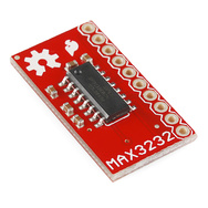
- Logic Level to RS-232 Voltage Level Converter - various options available, a cheap and easy one is the Sparkfun MAX3232 Breakout, shown below
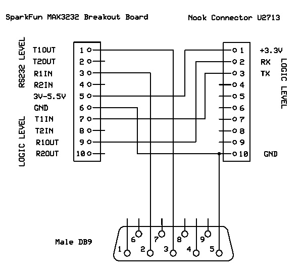
Circuit Diagram
Here are the connections you need to make. - see diagram and photos below for pins numbers and other details.There are three components diagrammed:
- The Nook Connector U2713, on the Nook ST main circuit board
- The MAX3232 board, purchased from SparkFun or elsewhere, to be mounted inside the Nook case.
- The DB9 connector and cable you provided, for connecting to the GPS or flight computer
Notes:
- This serial port solution only uses RX, TX - it does not include any hardware handshaking and works fine without it
- The MAX3232 is powered from the Nook - power consumption is miniscule
- Only signals are sent through the DB9 connection - there are no power connections either to or from the Nook ST
Minimize risk of damaging your Nook ST
If you don't have any experience soldering or hardware hacking, consider getting help. Check with a local robotics, ham radio or electronics club. There isn't a huge risk of causing damage to your Nook, but you need to be careful. You don't want to zap anything with static electricity, mash delicate parts or drop globs of solder on the board. If in doubt, buy a extra used Nook ST just for experimenting - they are $30 to $50 on Ebay and Craigslist.Open the Nook Simple Touch Case
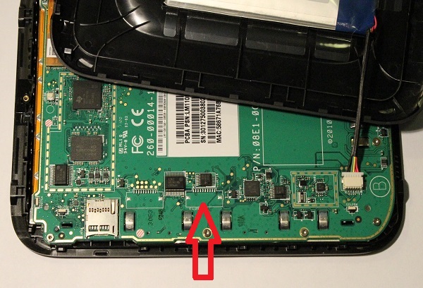
First, follow the instructions on this page and make sure the battery is disconnected.Locate U2713 Connector Outline and U2716 YE04 Voltage Level Translator
Find the unpopulated connector labeled U2713 on the main circuit board. It connects to U2716, which is a Texas Instruments YE04 voltage level translator in a TSSOP package. The YE04 translates voltage from 3.3v to a lower voltage (1.8?) used by the OMAP3621 processor.You need to solder small wires to the unused U2713 pads. The main board was designed to have a surface mount connector soldered in place on U2713, but it wasn't used. This is a common practice in circuit board prototypes and sometimes it carries over to production boards. The Nook main board has plenty of extra space for an unused connector - the large screen area primarily dictates the design.
Using a Connector on U2713
It's not necessary and extra work and parts to solder a connector to the U2713 connector. It's pretty easy to solder 30 AWG wires directly to the pads. However if you choose to use one, U2713 is designed for a 10 pin, single sided, 1mm pitch device with two larger grounded pads for securing it to the PC board. This is a common connector, and many variants are available on DigiKey and Mouser, some of which include the mounting tabs.Connector tips, if you decide to use one:
- Before you solder on a connector, use solder braid or a solder sucker to pull all the existing solder off all the unused pads, so the connector can lie flat on the board. The solder on the unused pads is a normal result of the manufacturing process.
- A connector with mounting tabls isn't necessary but if it doesn't have them, glue it in place so it doesn't pull loose and damage the pads.
- Depending on which connector you use, it may be necessary to chop a hole in the back of the case.
- The circuit board was probably designed to use a connector similar to Digikey part number A99963TR-ND, and you would need to get a matching connector of opposite gender and cable.
U2713 Pinout
Here are a couple close-up pictures of the connector outline, signal and mounting pads. The pin numbers correspond to the schematic diagram. The two mounting pads are grounded, so you can use one of them for GND instead of pin 10.I've numbered the pins 1 through 10 left to right. There are no numbers printed on the board, but pin 1 has a little arrow symbol. I don't know what pins 4 through 9 are connected to, if anything, past the YE04.
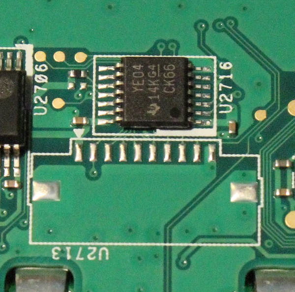
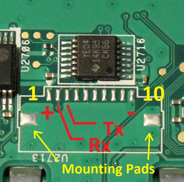
Soldering the Wires to U2713
Solder suitable length wires to the U2713 pads. There should be enough solder left on the pads from manufacturing - you won't need to add much. The shorter the wires the better, but it's not critical - you can actually run logic level signals pretty far, depending on the cable type and data rate. The wire length should ideally allow for mounting the MAX3232 board inside the Nook case, although you can mount it further away.It's pretty easy to solder pads with 1mm pitch if you have a little soldering experience. If you have a low temperature soldering iron, but tip is too large, you can file or grind the tip to a fine point and then re-tin it so the solder will stick.
Here are a couple close-up pictures after the soldering was performed. The soldering looks a little sloppy but it's not too bad. There is some gunk on the board, which is super glue and flux residue from a previous experiment. The connection on pad 10 could use a little more solder and pad 1 has a little too much - pin 3 is about right.
Soldering tips:
- Try to do the job right the first time - multiple heating cycles stress the board and pads
- Use a low temperature soldering iron with a small tip
- Keep heat low - high heat can cause the pads to pull off the board
- Solder the wires securely, and strain relive them with tape or glue
- Don't use excess solder, which can cause short circuits by bridging across adjacent pins
- Don't drop any solder on the board where it doesn't belong
- Don't try to use large gauge wires
- Don't use wire with insulation that melts easily during soldering - Kynar works great
- Be careful not to hit small components with the soldering iron and knock them off the board
- After you're finished, inspect your work carefully for solder bridges and poorly soldered connections
- It's nice but not essential to use flux removed to clean up the board when you're finished
Securing and Routing the Wires
Make sure you glue the wires to a blank portion of the board for stress relief. You don't want to pull the pads off the board. You can use gel-type super glue or hot melt glue. Don't power anything up until the glue is dry to make certain it's not conductive.Ideally you should avoid routing the wires directly over ICs and signal traces to avoid interference, but it's probably unavoidable. The communcation is low speed so there shouldn't be a problem. However if you see intermittent data problems it could be an issue.
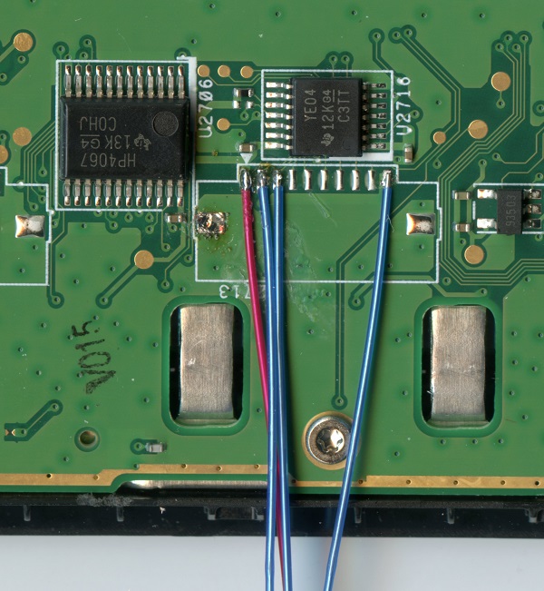
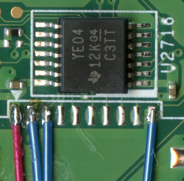
Soldering the Wires to the MAX232 Board
Solder the wires from U2713 to the MAX3232 board, following the wiring diagram.Attach the RS-232 DB9 Cable
After you've soldered the small wires to the Nook ST and the MAX3232 board, it's time to connect the RS232 cable so it can talk to the outside world. Follow the RS-232 wiring in the circuit diagram. Before you solder the wires, chop a hole in the back of the case and feed the wire through. Make sure the cable is glued or fastened somehow for strain relief.You can use an old serial cable or old USB cable and fresh DB9 connector, and chop the cable to your preferred length. Old serial port cables tend to be thick and contain wires for all the pins. USB cables have 4 wires plus a shield and tend to be slimmer.
Check for continuity on pins 2, 3, and 5 before soldering anything. If the cable has a shield, generally it's recommended that the shield is connected to ground on one or the other devices, but not both. Probably you will want to use a male DB9 connector, but first check the gender of the connector on your flight computer or GPS.
Alternately you may wish to mount a connector on the back of the Nook case. There is probably room to do this, depending on the connector, but I haven't checked it out.
Mount the MAX3232 Board
There is sufficient room to mount the MAX3232 board inside the Nook ST back case. A good spot is between the battery and the switch mount. To get extra clearance, grind flat the little plastic center fin so the circuit board will fit flush against the case. The board should be secured in place with tape or glue. It must be insulated with tape from the main circuit board so there is no possibility of causing a short circuit. Route the wires where they won't get pinched, and glue or tape them in place.Finish Up
Before you close the case, double check your wiring against the diagram. Make sure there are no solder bridges. Check the wire routing to make certain all are secure and have strain relief.Attach the battery and make sure everything is working correctly. If not go back over everything and look for errors. Sometimes things go bad - that's just part of hardware hacking and you have to live with it and learn. Rarely it's not even your fault.
Close up the case in the reverse order of assembly. Make sure you don't pinch wires or crush anything. Don't lose the T5 Torx screw!
Developer Notes
In order to use the serial port, permissions must be given using the console command, chmod 0666 /dev/ttyS1 - this is incorporated into a later version of the Top Hat or the rooted OS files, so if you're running a recent version don't worry about it.. If the chmod command is not performed, the ttyS1 port will not show up in the Top Hot device selection menu.You can run the chmod command remotely from a PC by installing a program such as ADB Konnect on your Nook - this allows remote connections over WiFi. An Android development package installed on your PC will include the adb.exe utility - you then run the command: adb connect yourNookIPaddress from a command window on the PC. Once the connection is established, you then run the adb shell command, which give you a remote shell with a # prompt. From that prompt, you can then run the chmod 0666 /dev/ttyS1 command.
For custom applications, port speed can be set with the command: stty -F /dev/ttyS1 9600, where 4800/9600/19200/38400/etc. are typical speeds.This command sent from ADB will not persist after a reboot - altering config files is necessary.